I designed a fully revertible modification for a Vornado 633DC fan so I could control it remotely over WiFi. The final result is concealed entirely within the fan’s housing, leaving no visible modification.
If you’re interested in building one yourself, I’ve published the schematic, BoM, and PCB design on OSHWLab. In terms of firmware, I used ESPHome with an external component, for which the source code is available on GitHub. The rest of this post covers the research and development that went into the project.
How it began
When I first bought this fan I chose it because it uses a DC motor which, compared to AC counterparts, use less power, and run quieter. By adding a smart plug between it and a power outlet, I could give it a basic form of on/off remote control. But this presented a problem: If I wanted to adjust the speed I would have to physically interact with the fan!
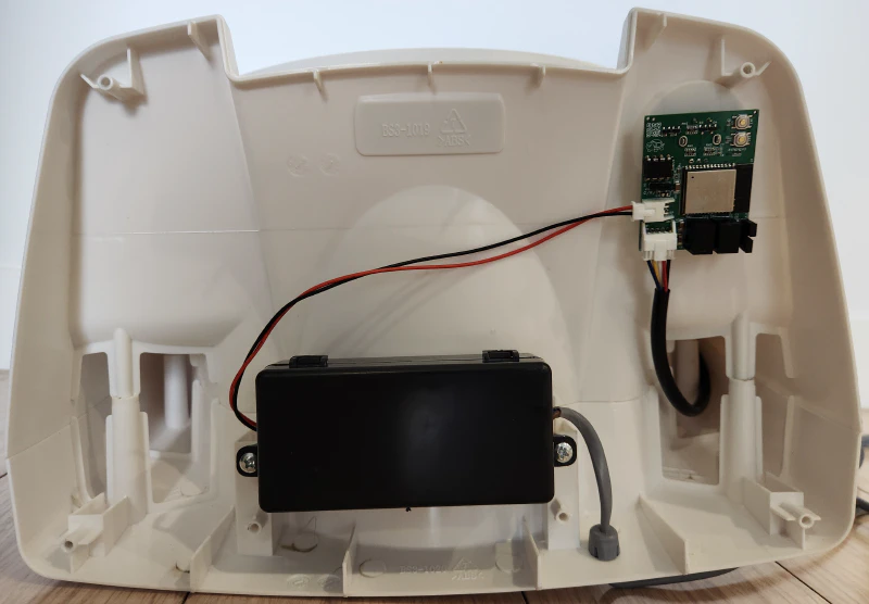
Obviously, I needed to see what could be done about this, and so I took a look at the inside of the fan. Six screws later, and I was greeted with a surprisingly spacious interior.
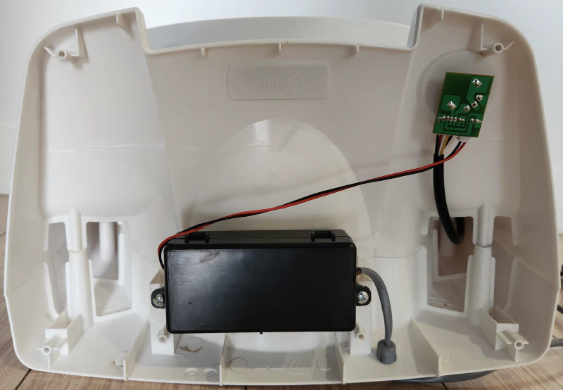
Inside were two components:
- An AC-DC converter
- A small PCB which held the potentiometer used for the speed control dial
Everything joined up via a 2-pin and 5-pin connector on the PCB. From there, it was a straightforward matter of measuring voltages and continuity to work out what connected to what: the 2-pin connector was offering 24V DC. The 5-pin connector was what went off to the motor itself. Two of its pins were passing through the 24V DC and ground directly. Two more pins were connected to the potentiometer. The fifth pin was not connected.
With this, I concluded that the variable resistance between the two potentiometer pins is used to control the speed of the motor. From here the idea started to form: if I could produce a variable resistance digitally, I could control it remotely, thus avoiding the need for physical interaction.
Potentiometers Go Digital
A traditional potentiometer has three pins: one at each end (A & B), and a “wiper” pin (W). When the dial is rotated, an electrical contact moves across a conductive surface which is connected to A & B at either end. This electrical contact is connected directly to the wiper pin. As the dial rotates clockwise, the total distance that electricity must travel to get from A to W increases, which results in an increase in resistance between those pins ( ). At the same time, the distance (and thus resistance) between B & W decreases ( ). Anti-clockwise rotation inverts this behaviour.
In the case of the fan, only two potentiometer pins are used: W & B. This means that a decrease in potentiometer resistance represents an increase in fan speed ( in the animation above).
Digital Potentiometers (or digipots) are an IC designed to mimic the function of their analogue counterparts. Like a traditional potentiometer, they’ll have three pins mimicking the A, B, W functions (as well as a few more pins to allow a host device to control the IC).
In lieu of a single conductive surface for a wiper to sweep across, digipots usually comprise several resistors wired up in series, known as a “ladder”. Between each of the resistors a connection to the wiper pin can be made. Each of these connections is controlled so that there is only one completed connection to the wiper pin at any given time. The result of this is the ability to vary and , like a regular potentiometer, albeit with a finite number of discrete resistances.
In order to test it out, I made an ESPHome external component (i.e. a driver for the digipot, compatible with ESPHome), and connected everything up on a breadboard.
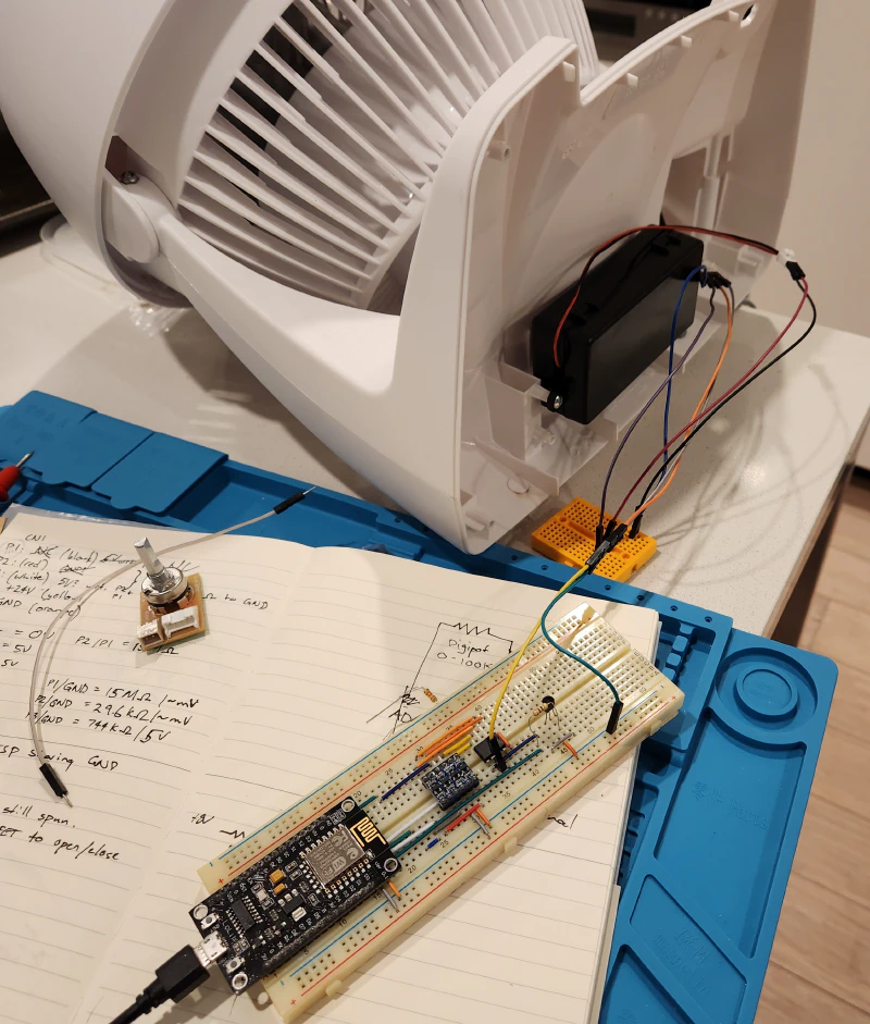
With on/off & speed control proven out, I was confident the concept would work. The next challenge was designing a custom PCB that could fit within the fan’s existing housing while holding all the necessary components.
Designing a PCB
Designing a custom PCB meant carefully selecting components and ensuring everything would fit within the fan’s existing housing.
Component Selection
I spent more hours than I care to admit reading through datasheets to increase my confidence that the assembled PCB would simply work. A breadboard test with a dev board is one thing, but I didn’t have the space (nor the desire) to use an entire dev board inside the fan, where only a small subset of a dev board’s functionality was actually needed.
The majority of the time went into researching power requirements for the main components. These components run on 3.3V or 5V. Plenty of options exist for stepping down 24V to these voltages, to the extent I was spoiled for choice. What ultimately tipped my favour toward the chosen components is their relative simplicity: aside from the regulators themselves, nothing is strictly required. A few common capacitors are nonetheless added by recommendation of the datasheets for improved voltage stability.
The digipot would have been a close second on time spent researching. It faced a similar problem of an abundance of options, but also faced the problem that ESPHome didn’t support any suitable digipots out of the box, which meant I would have to write my own component code (essentially a driver). This is where most of the waiting came from, because I opted to order the intended digipot to test my code with before proceeding toward the PCB design stage.
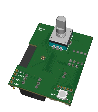
I also opted to include a rotary encoder in place of the original potentiometer. Rotary encoders don’t indicate resistance, but instead emit signals to indicate whether they are being rotated clockwise or anti-clockwise. My goal here was to still allow the use of a physical interface for controlling the fan speed. In theory I could have used a potentiometer, but this would mean needing to convert an analogue signal into a digital one which, in my testing, was fraught with reliability issues due to electrical noise. The practical consequence of this decision was simply that the dial can spin infinitely in either direction instead of having a defined start and end point.
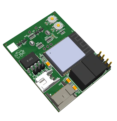
For the SoC, I opted to use the ESP32-C6-WROOM-1. ESP32 is a pretty popular family of SoCs, and there’s a lot to choose from. I chose the C6 as a future-proofing effort because it has support for ZigBee & Thread protocols, as well as WiFi which is what I’ll use for now (it’s early days for ZigBee & Thread support with ESPHome).
Finally, because I could, I added an RGB LED to provide user feedback such as green for low speed, red for high speed, etc.
Physical Constraints
The original PCB featured a potentiometer with a threaded base, with which a nut was used to secure it to the fan’s housing. I designed my PCB to use the same mounting mechanism.
I also had to make sure that the PCB would fit within the space available: there’s a lot of empty space inside the fan’s housing, but only a limited amount which a flat PCB can work with before it hits some protruding plastic.

The original PCB also had its power input plug positioned such that it was putting some strain on the power cable. I opted to move it on my board to alleviate this.
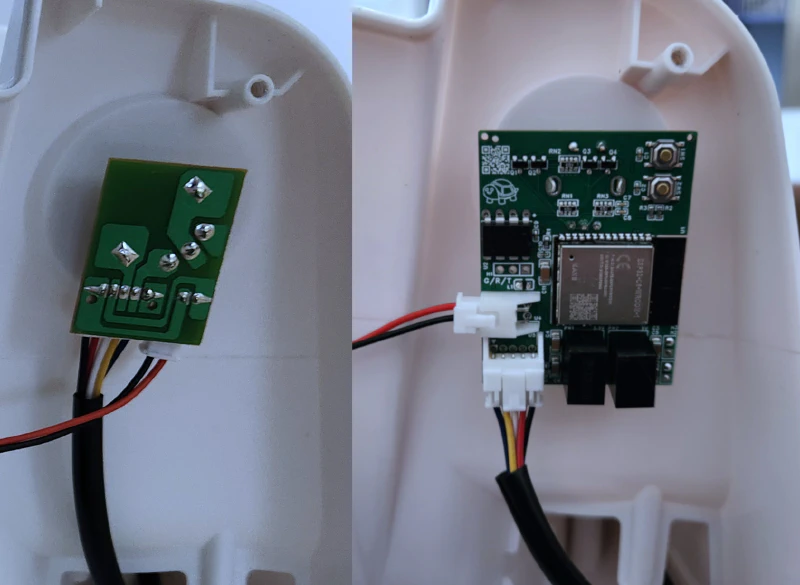
Assembly
The PCB was ordered from JLCPCB, where I opted to have most of the components pre-soldered. This left only the through-hole components, the LED, and the ESP32 module requiring manual soldering.
ESPHome Configuration
The external component mentioned earlier handles the interfacing between ESPHome and the digipot, but the final PCB includes an RGB LED and a rotary encoder (with a push button inbuilt), all of which need configuration to actually be useful. The bulk of the configuration file ended up being the code necessary to support these additional components, with the core digipot/fan control only taking up 13 lines.
This version of the configuration file provides:
- Remote fan control
- Rotary encoder as physical speed control, with push button for on/off
- LED used as a status indicator (e.g. flashes when connecting to WiFi)
- LED temporarily illuminates with a green through red blend in response to physical fan speed adjustments
Results
I thought about showing a video of the final product in action, but with the entire modification concealed within the housing of the original fan, I’d just be showing a video of a fan. A video just didn’t feel like it did it justice.
But when I consider the many ways I could have gone about this project, the many features I could have added or avoided, and the many hours I spent researching, testing, and designing this thing, I can comfortably say I’m happy with the result: a fully revertible modification which requires no permanent alteration to the original fan, while also preserving the original manual interface.
Most importantly of all, when I just really need a breeze, no longer would I have to consider physical interaction with the fan to achieve it.